To Create a Socially-Distanced Queue
-
Start the
Socially-Distanced Queue Tool command
 .
.
The command requires an accessible space to start. If an accessible space is not defined, the command start methods are disabled.
-
The Socially-distanced Queue Options dialog is visible during the
command. Use it to configure social distancing in the queue.
- Define the Social distancing value (default is 2.0 meters or 6'7" in imperial units).
- Select a Layout style. Choose one of these:
- (Optional) Review the Object count which displays the number of valid queuing locations in the queue.
- (Optional) Note the Sequence length which displays the total length of the queue path.
-
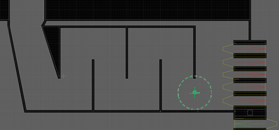
The command prompt directs you to
"Select location of Socially-distanced Queue
front".
A social distanced queue location marker is attached to the pointer.
Click where you want the front of the queue to be. -
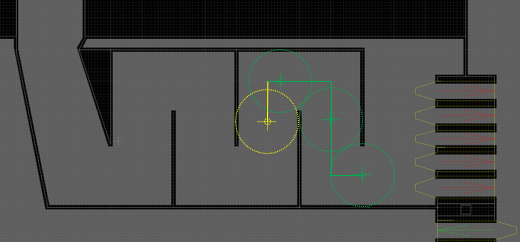
Begin drawing the queue shape by clicking to enter the key points
where the queue changes direction (command prompt:
"Select next point along Socially-distanced Queue
path. Press <Enter> to finish.")
After each key point, the Socially-distanced personal space circle is shown at the mouse position or the current queue tail.
For the Automatic spacing layout, the queuing locations are automatically calculated along the queue path as it grows.
-
Continue drawing the queue shape.
- A green queue location marker indicates a valid location.
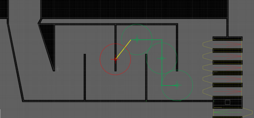
- A yellow queue location marker indicates the location overlaps a previous location.
- A yellow line segment in the queue path indicates the segment is too short for effective social distancing.
- A red queue location marker indicates the location is outside the accessible space, and is not counted.
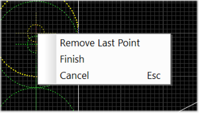
- (Optional) If you make a mistake adding a queue path point, you can "step back" to fix drawing errors dynamically.
- When you have finished drawing the desired queue shape, press the <Enter> key to finish.
-
Once the queue path is created, you can adjust all click-point
locations to correct any errors (command prompt:
"Adjust Socially-distanced Queue path as needed. Press
Enter to create Delay Points.")
-
An edit handle (small green square) is placed at each
click-point. Grab the handles to adjust and change path shape.
The Queue locations dynamically adjust as you move the edit handles.
For the Automatic spacing layout, any large enough gaps are filled with new location markers. The Object count goes up or down as the edit handles are moved.
- (Optional) To drop an edit handle, click again at the desired point. The queue path reshapes and the locations are updated.
- Once you are happy with the queue shape, press <Enter> to proceed.
-
An edit handle (small green square) is placed at each
click-point. Grab the handles to adjust and change path shape.
- Upon completing the command, the Set Delay Point Properties dialog is displayed.
- Click OK to close the dialog and create the Delay Point sequence for the socially-distanced queue.
- Link the front Delay Point to your model's service points, using your preferred link method (for instance, Entity Choice: Fewest Occupants).
-
When linking to the back of the queue,
links are subject to target availability which
depbacks on Delay Point capacity.
- Once an entity is on-route to the back Delay Point, no other entities are sent there until that entity reaches the back Delay Point.
- Then a single other entity can be sent to the back Delay Point, and so on.
To deal with this:
- Place a Focal Node before the back of the queue (Focal Nodes don’t have capacity constraints).
- In the Focal Node, uncheck the Use target availability option on the Links tab, and link the Focal Node to the back Delay Point.
- To sback entities to the queue, link them to the Focal Node.
- Entities cluster around the Focal Node once the queue is full. This indicates either:
Failure to this means entities get trapped at the link sbacking object(s).